This board replaces the hand-wired block of switches in the original article. I don't think it is in any way anachronistic. First off, the article was really about the circuit design and the case and switch mounting is barely even mentioned. Secondly, I think it's clear from Titus's published comments that he built a hand-wired version first, and the switches were probably just moved from that prototype to the pcb prototype. Had he had more time, he might have made a pcb for the switches himself (and a backplane, but that's another project!).
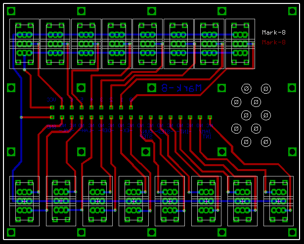
Each switch position is laid out with three sets of holes so as to take either an SPDT or a DPDT switch (or in some cases an SPST may be used). The spacing is a little broad in order to accomodate the very wide paddles (0.6") that Titus used (the same type used in the Altair et al). These switches are hard to find nowadays, but the 0.453" paddle switches that are available work look fine to me.
I bought 16 C&K 7201J60 DPDT paddle switches from Jameco (part # 163336) and 6 momentary NKK M2015TNW01-EA SPDT switches from Mouser (Part # 633-M201501E). You could buy them all from Mouser, but they only have narrower 0.365" paddles. Replace the paddles on the momentary switches with ones removed from the Jameco ones. If you can't get the wide paddle switches, you could use NKK M2012TNW01-EA switches from Mouser instead.
The wires are run from the labeled solder points in the center through the strain relief holes on the right and then to the appropriate Molex connector.
ERRATA: (1) on the switch board, the LAL and LAH markings are reversed. (2) despite the schematic, the JAM switch is connected to the NC contact, not the NO.